Showing posts with label Airsoft. Show all posts

17 January, 2016

Casualty Simulator Android App

A friend was discussing with me various prop idea which we could make with Arduino in particular, but there are "virtual props" that you can build in software. Virtual props are particularly well suited to logic driven props which are hard to build in the physical world.

As an example I built this Casualty Simulator for Android DEMO. This is a demo intended only as a proof of concept. It is not intended for use as is, although it should be usable with limitations.

It should run on fairly old Android devices, but may struggle if they are really underpowered.


Basically it is an Android app which is designed to be running on an Android device placed on a casualty which will be carried on a stretcher. The app detects if the casualty is pitched about dangerously and every time that happens, the app cries out in pain and the casualty loses health.

When the casualties health reaches zero the casualty is dead. The players can "Give Treatment" to the casualty a maximum of three times, which will add 20 health points back. This is to simulate bandaging, transfusion or adrenaline treatments.

Note that the players cannot give treatment to a dead casualty, nor can they heal a healthy casualty above 100 health.

There is an audio heartbeat monitor which slows down as the casualty gets closer to death. This gives the players some approximate feedback on the casualties status. To get an accurate status the players can click the "Check Health" button as often as they like.

If the casualty dies there is an audio feedback of a heartbeat monitor flat-lining, and on screen text to alert the players.

To prevent cheating the app displays a simple log of the starting and stopping of the app along with some other useful info.

To reuse again, simply quit and restart the app. Start/Stop acts like a play and pause function, not a restart.

Please note you need to long press the Start/Stop button to minimise accidental Start Stops.

Finally, this is a concept demo, if anybody wants me to develop it further, please contact me through the contact page. I guess if anybody wants to use it, they will want to be able to edit all the parameters, such as health, sensitivity, treatments.

Installation Instructions


Before you can click on the download link you must enable the ability to install software from "Unknown Sources" and you must manually un-install any earlier copies of the software.

"Android protects users from inadvertent download and install of apps from locations other than Google Play (which is trusted). It blocks such installs until the user opts-in Unknown sources in Settings > Security, where you will see an option similar to the option shown below. To allow the installation of applications from other sources, users need to enable the Unknown sources setting on their devices, and they need to make this configuration change before they download your application to their devices." 


The text may also say "Allow installation of apps from sources other than the Play Store."
Note: You would be wise to disable this option after you have successfully installed the software.


From your android device you can now access the download link and the software will be installed on your device. The download link is available after you accept the Warning and Liability Notice below.


DISCLAIMER OF WARRANTIES AND LIMITATION OF LIABILITY

Software downloaded from the CrapWorks web site or from other sources is provided 'as is' without warranty of any kind, either express or implied, including, but not limited to, the implied warranties of fitness for a purpose, or the warranty of non-infringement. Without limiting the foregoing, the CrapWorks makes no warranty that:


  • the software will meet your requirements
  • the software will be uninterrupted, timely, secure or error-free
  • the results that may be obtained from the use of the software will be effective, accurate or reliable
  • the quality of the software will meet your expectations
  • any errors in the software obtained from the CrapWorks web site will be corrected.
  • the software is complete and free of defects


Software and its documentation made available on the CrapWorks web site:

  • could include technical or other mistakes, inaccuracies or typographical errors. The CrapWorks may make changes to the software or documentation made available on its web site.
  • may be out of date, and the CrapWorks makes no commitment to update such materials.

The CrapWorks assumes no responsibility for errors or ommissions in the software or documentation available from its web site.

In no event shall the CrapWorks be liable to you or any third parties for any special, punitive, incidental, indirect or consequential damages of any kind, or any damages whatsoever, including, without limitation, those resulting from loss of use, data or profits, whether or not the CrapWorks has been advised of the possibility of such damages, and on any theory of liability, arising out of or in connection with the use of this software.

The use of the software downloaded through the CrapWorks site or other sources is done at your own discretion and risk and with agreement that you will be solely responsible for any damage to your computer system or loss of data that results from such activities. No advice or information, whether oral or written, obtained by you from the CrapWorks or from the CrapWorks web site shall create any warranty for the software.


or 

07 April, 2015

M1911A1 Real Wood Grips Part 1

Over the Easter Holiday I decided to make a set of real wood grips for my M1911A1 to replace the nasty dark brown plastic grips which were on the pistol.

The M1911A1 is part of my Namsofting Loadout. Brown plastic grips are actually historically accurate on 1911s from WW2 onwards, but I like to imagine my 1911 was in fact an upgraded personal item rather than standard issue.

I could have bought some mass produced wooden grips cheaper, but the wood on those things is usually some nasty crap which was never on a real piece. I selected American Black Walnut, which is authentic for the M1911 and a premium quality woodworking timber.

This post is part one of a two part post. In this post I will cover how I made the grips and in the next post I will cover checkering. Checkering is the gunsmithing term for the diamond grip pattern. I think the smooth grips are very nice as they show the wood grain pattern to full effect due to their smoothness and uniformity. Much of the grain effect will be lost with the checkering.

As usual for my posts, here is a picture of the finished grips fitted to the M1911A1...

The CO2 mag is not exactly authentic! :-/
I started by finding somebody elses DXF files from a forum. I imported them into Solid Edge ST7, but ended up doing so much revision to them that I might as well have just drafted my own from scratch.

Revised DXF in Solid Edge ST7
I imported the revised DXF into CamBam and generated the toolpaths...

The most awesome CamBam
From there I generated G code which I fed into my CNC Router to cut the grips.,.

A clean workshop is a safe workshop! *cough*
This is how the grips come off the CNC Router...


As you can see there is still a lot of work to do on these grips to get them to a finished state. I finished cutting the grips out with a fret-saw and made this little jig to enable me to sand them on my belt sander without sanding my fingertips off (again!!!).


This little jig was made with 2 dowels and a board with similarly spaced holes. It enabled me to sand the grips while only sanding one knuckle bloody. Progress!!!


The sanding with a 400 grit belt really brings out the woodgrain.

I repeated the sanding on the other grip and test fit the grips to the pistol. They needed quite a bit of hand carving on the back face to make them fit the pistol correctly.


Two coats of Danish Oil really makes the wood-grain pop...

Before and After Danish Oil
The lustre turns much more matt and natural as the Danish Oil soaks into the wood.

Here are the wood grips side by side with the old plastic ones...


You can see that the lustre has gone.

Finally, here is another picture with the grips fitted to the pistol..


I am very happy with the finished result, so much that I am really reluctant to checker them now. I think I will make a second set and keep whichever ones I like best.

Thanks for reading and lookout for part two, coming as soon as my checkering tools arrive. :)
  

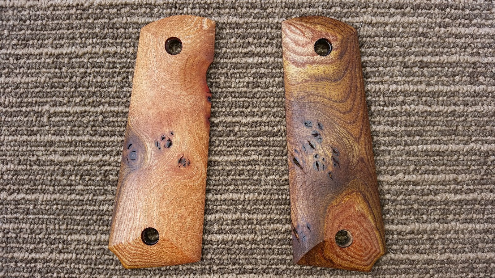
Update: The checkering tools have still not arrived so I made these grips from a very nice piece of Burr Elm.

Scottish Burr Elm Grips


The figuring on this wood is very nice


These were also popular.


09 January, 2015

Rifle Rack Construction Method and Assembly

I have been asked for details on how I constructed my Easy Build Compact Rifle Rack. Here are some pictures that may help you make sense of the cutting process and the assembly.

A model of the finished rack

I started by cutting the basic parts from 20mm thick board. On the left you will see both sides cut from the same board. On the right you will see six parts all the same width. The top two are the top rail assembly, the bottom four make up the base assembly.

Note: For my American friends, I am sorry the measurements are metric, however most of them are actually multiples or fractions of an inch so it would not be too difficult to follow along.


Overall dimensions of the parts

 Here is a close up of the top rail assembly and the layout of the rail.

Marking out the top rail

 After cutting it looks like this.

The top rail after it has been cut with a jigsaw
 Next I cut the oval holes in the base plate. These holes must align with the top rail and be equally spaced.

Each hole is two 60mm diameter circles

After cutting it looked like this.

I cut the holes with a 60mm holesaw and a jigsaw

 The sides are cut from the same board.

Layout of the sides
After they are cut they look like this.

I cut the sides with a jigsaw.

With all the parts cut out they should look like this.

I also rounded over the edges with a round-over bit on my router table

In the next images I will show the basic assembly. So that you can follow along I have coloured each part.

If Skittles made rifle racks

I first assembled the base and the top rail. I used a biscuit jointer and glue. These could simply have been glued with the parts butted up against each other or possibly with dowels or even screws.

The base and top rail assembly

I then joined the base and top rail assembles to on of the sides, checking for square.

It is critical to check for square
Then the other side is joined, again checking for square. After it was all solid, I trimmed the front of the top-rail assembly flush with the sides. This could have been avoided by better planning at the design stage of these drawings.

Measure twice cut once applies even in the virtual domain

This is the actual finished piece. You can see it differs only slightly from the drawing.

My original rack dry fit (not yet glued)
I hope this short pictorial explanation will help you understand the construction of the rack.

Please be aware like all my blog these drawings are protected by the Creative Commons Attribution-NonCommercial-ShareAlike 4.0 International License

Thanks for reading! :)

08 January, 2015

Easybuild Compact Rifle Rack

I had a need to build this compact rifle rack to fit inside a closet. The requirements were that it had to;
  • be easy to build
  • fit a range of rifles from short carbine to long rifle size
  • be stable
  • fit in a 460mm(18 inches) space.
I built this little rack out of reclaimed pine shelving which came from a warehouse which closed down.

Read all the way to the bottom if you are interested in one of these racks

My finished compact rack
The reclaimed shelving I got from freecycle. It is about 20mm (6/8 inch) thick, close grained pine, with very few knots. The closer the grain the slower the growth and generally the stronger the wood.

The reclaimed shelving was quite grubby
I drew out the shapes for the rack and cut them on the table saw and the hand held jigsaw. after a fair bit of sanding with the orbital sander the wood began to show through. It was very messy, and the worst kind, dust!

A part sanded board
Options for fixings were, screws, dowels, glue but I decided upon #0 biscuits. Biscuits are a wooden spline which sits in a slot cut by a biscuit jointer. These are glued making for a much stronger joint than simply with glue alone.

Biscuit jointer, a biscuit and the joint
With all the parts cut, sanded and the edges rounded over on my router table with a round-over bit, I was able to dry fit (with no glue) all the parts together for a first look. This next image lets me explain how the rack will work. The fore-stock of the rifles will rest against that wavy top rail. The gummy-bear shaped hole on the base allows two thirds of the butt-stock to sit in the hole while one third of the but stock rests on the base plate but not in the hole. This causes the rifle to tilt slightly backwards and rest against the wavy top rail. If this works the rifles should be stable enough in the rack.

The biscuit joints allow it to be test assembled without glue

Ok, I am happy with the design, now for the glue-up and clamping after checking for square. Note that I used "Gorilla Glue". This was an experiment, usually I would use a PVA based glue for furniture. On reflection, if I were to build another I would go back to a PVA based glue. I have now read several reports where PVA glue beats expanding polyurethane glues like Gorilla Glue, hands down in almost all situations. Click here to see a video of PVA versus Gorilla Glue.

I never have enough clamps

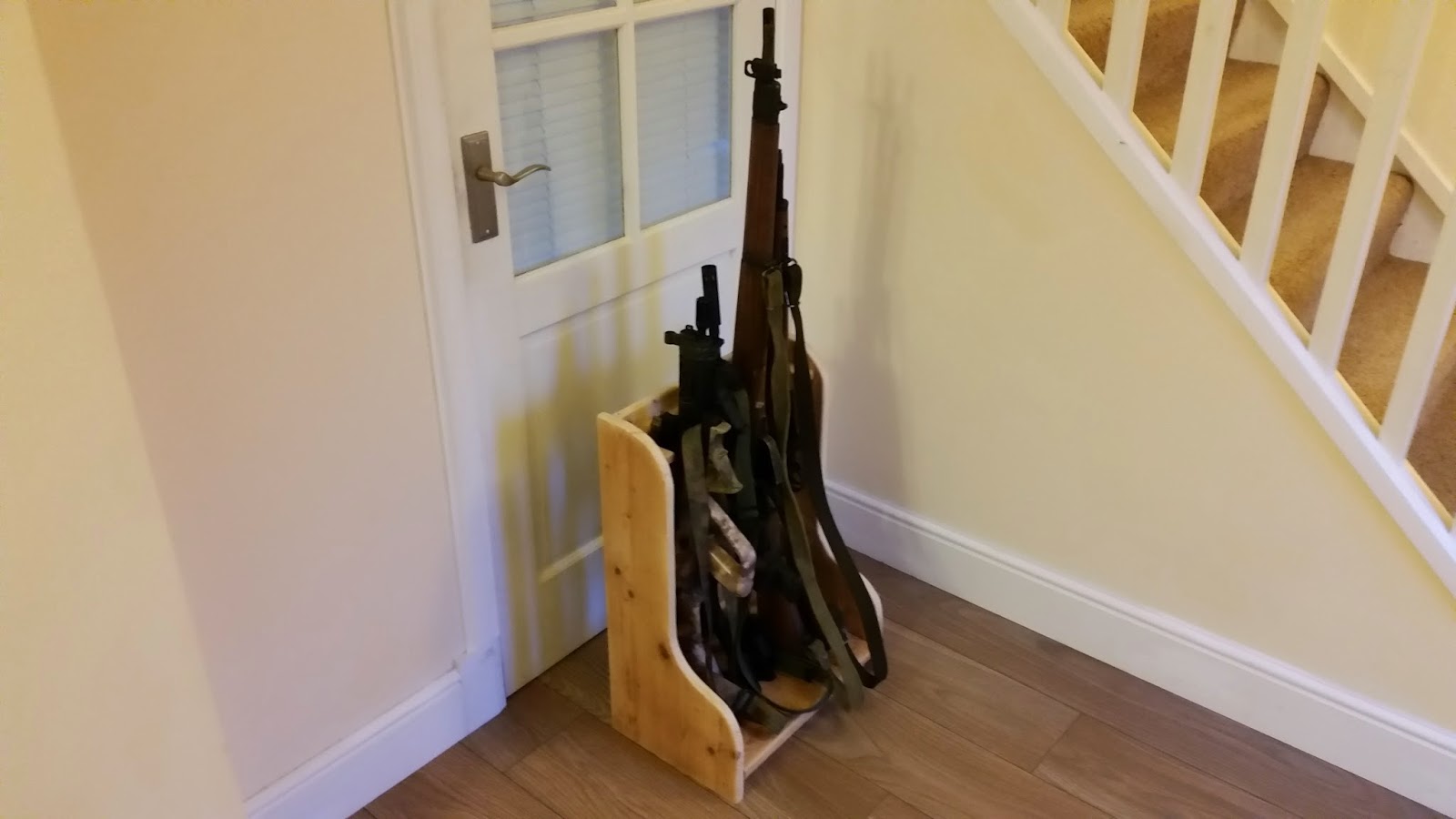
Here is the finished piece. Is it stable? Yes it is! I am able to pick up the entire loaded rack and move it around without the rifles all toppling around. Does it take a range of rifles? Yes it does!

L to R: AUG Carbine, SIG 552, XM177e1, M14, Lee Enfield No4.

Was it easy to make? Yes, with the correct tools, particularly the biscuit jointer. Other tools I used are my table saw, jigsaw, table router and round-over bit a mallet and some clamps.

Small but mighty

Does it fit the 460mm (18 inch) space? Yes it does with a size of 460mm wide (18 inches), 300mm deep (12 inches) and 610mm tall (24 inches)

In situ

In conclusion, I think the design worked really well but if there were a next time there are only two things I would do differently:
  1. I would use a PVA glue and not a Polyurethane based glue, and
  2. I would not use a reclaimed board, I would build it from nice furniture grade Birch plywood.
IMHO, This project was definitely a success. I have still to give it a finish. I will probably use Danish Oil or even a dark stain. When i make up my mind I will post another photograph.

If you are interested on building your own, if I get enough people wanting to purchase a self assembly kit to make it financially feasible I may make a few self assembly kits available. All you would need to do is glue it up and paint. I would do all the cuts, jointing and supply the biscuits.

Update: I have added another blog post with relatively detailed technical drawings here.

Otherwise, if a self-assembly kit might interest you please click here.

08 May, 2014

Stand-off scale Light Mortar Theatrical Prop


I was asked to make a 60mm Light Mortar non-firing theatrical prop as a commission. The brief was that it had to;

  1. be cost efficient.
  2. accept some inert 60mm training rounds that the client already has.
  3. be stand-off scale. i.e. Give the impression of the item without being an exact replica.
  4. be robust.
  5. be incapable of ever firing a projectile should it be stolen and modified.

As usual this is not a build tutorial and do not try this at home.

This is what I was aiming to replicate as a 1:1 stand-off scale model...
image copyright ZM Tarnow.
This is what I came up with...


It was made out of some scrap scaffolding tube, a scaffolding foot, an old car jack and an old spacesaver wheel that were donated by various people. To this donated pile of bits, I had to buy two small pieces of steel plate, 68mm plastic pipe, some plastic brackets, a delrin (engineering plastic) plate, various M10 and M6 bolts, welding rods and two tins of spray paint.

That is a lot of steel to cut. Luckily I have two of these Evolution saws, a circular saw and a small mitre saw which can cut through steel like butter...

With all the parts cut, I set about welding with my little stick welder. Hands up I am not a good welder. I weld once or twice a year, and I do it so infrequently that its always a learning experience for me. Because the donated steel was galvanised (with zinc), I had to sand off the zinc layer where I was going to weld. Welding with zinc can cause troubling health problems.


This is the first fit. Note the mole grip holding it together...

I found cans of this this nice 'Soviet Green' colour in Lidl. Here you can see the prop in it's three parts. In use it slots together and stands solid...


The prop cannot be aimed, as it has no aiming device. It cannot be adjusted as it is welded solid, and the plastic pipe and fittings are incapable of containing energy. Therefore it is truly non functional.


Thanks for reading. :)